Node Method or Node Voltage Method
Nodal analysis provides a general procedure for analysing circuits using node voltages as the circuit variables. Nodal analysis is based on Kirchhoff’s Current Law (KCL). This method has the advantage that a minimum number of equations are needed to determine the unknown quantities. It is particularly suited for networks having many parallel branches and also when there are current sources in the network. Nodal analysis is applicable to both planar and non-planar circuits.
To determine node voltages, the following steps are required:
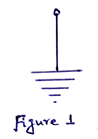
Step 1) Let there are n number of nodes in the circuit. Select a node as the reference node or datum node. Assign voltages V1, V2,…..,, Vn-1 to the remaining (n-1) nodes. The voltages are referenced with respect to the datum node. The datum node is commonly called the ground since it is assigned to have zero potential. A reference node is indicated by the symbol shown in Figure 1.
Step 2) Apply Kirchhoff’s Current Law (KCL) to each of the (n-1) non-reference nodes. Use ohm’s law to express the branch current in terms of node voltages.
Step 3) Solve the simultaneous equations to obtain the unknown node voltages.
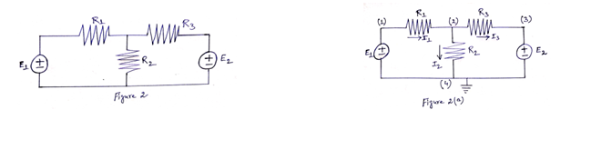
Consider the circuit shown in Figure 2. The circuit in Figure 2 is redrawn in Figure 2(a) where there are four nodes [represented by (1), (2), (3) and (4)]. Node (4) is the datum node (V4=0), while nodes (1), (2) and (3) are assigned voltages V1, V2 and V3 respectively. Here, node voltages are defined with respect to the reference node.
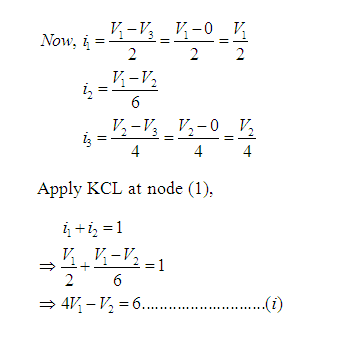
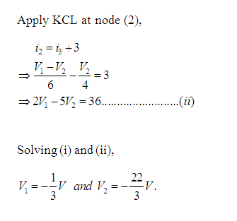
Problem 1: Obtain the node voltages in the circuit of Figure 3.
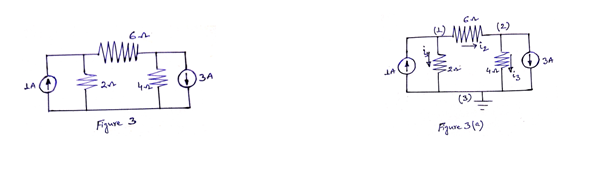
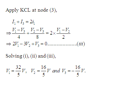
Solution: Here, there are three nodes [represented by (1), (2) and (3)]. Voltage of node (1) is V1, node (2) is V2 and node (3) is V3.Consider node (3) as reference node and grounded. So, V3=0. [See Figure 3(a)]
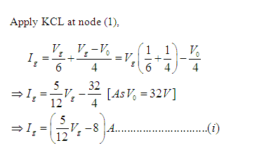
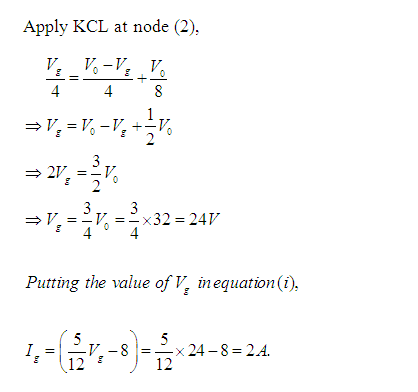
Problem 2: Determine current Ig in the electric circuit shown in Figure 4. Take V0=32V.
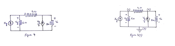
Solution: Here, there are three nodes [represented by (1), (2) and (3)]. Voltage of node (1) is Vg, node (2) is V0 and node (3) is V3.Consider node (3) as reference node and grounded. So, V3=0. [See Figure 4(a)]
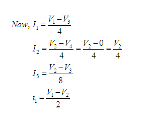
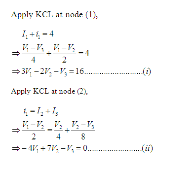
Problem 3: Obtain the node voltages in the circuit of Figure 5.
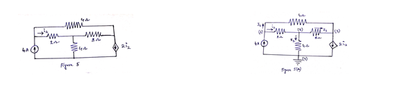
Solution: Here, there are four nodes [represented by (1), (2), (3) and (4)]. Voltage of node (1) is V1, node (2) is V2, node (3) is V3 and node (4) is V4. Consider node (4) as reference node and grounded. So, V4=0. [See Figure 5(a)]
Nodal Analysis with Voltage Sources
We now consider the following two cases.
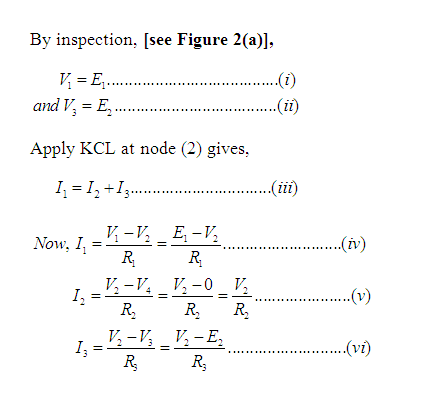
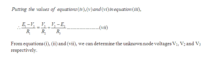
Case I: Let avoltage source be connected between the non-reference node and reference node. Here the voltage at the non-reference node is equal to the voltage of the voltage source. For example, by inspection, [see Figure 2(a)],

Thus our explanation is somewhat simplified by this concept of the voltage at this node.
Case II: If the dependent or independent voltage source is connected between two non-reference nodes, then these two non-reference nodes form a supernode. Here, we apply both Kirchhoff’s current law and Kirchhoff’s voltage law to determine the node voltages.
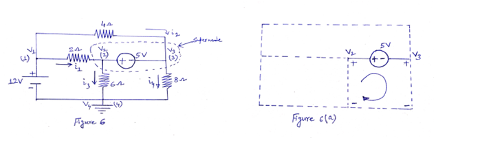
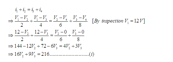
Here, there are four nodes [represented by (1), (2), (3) and (4)]. Voltage of node (1) is V1, node (2) is V2, node (3) is V3 and node (4) is V4. Consider node (4) as reference node and grounded. So, V4=0 [see Figure 6].
In Figure 6, nodes (2) and (3) form a supernode. We can solve nodal method by applying KCL, which requires knowing the current through each element. But there is no way of knowing the current through a voltage source in advance.
Now KCL must be satisfied at a supernode like any other node. Hence, at the supernode,

Note:
- The voltage source inside the supernode provides a constraint equation needed to solve for the node voltages.
- A supernode has no voltage of its own.
- A supernode requires the application of both KCL and KVL.
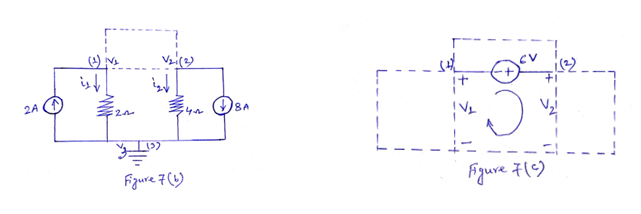
Problem 4: Find the node voltages in the circuit shown in Figure 7.
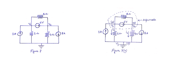
Solution: Here, there are three nodes [represented by (1), (2) and (3)]. Voltage of node (1) is Vg, node (2) is V0 and node (3) is V3.Consider node (3) as reference node and grounded. So, V3=0. [See Figure 7(a)]
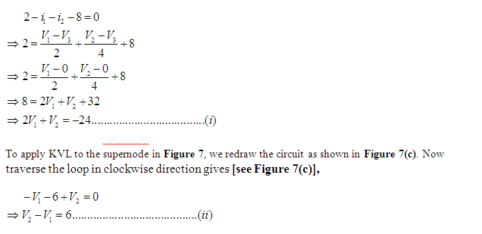
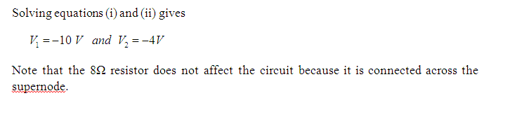
The supernode contains the 6-V source, nodes (1) and (2) and the 8 Ω resistor. Applying KCL to the supernode as shown in Figure 7(b) gives